Device and end-user protection against potentially damaging voltage, current, and temperature conditions are needed in applications like USB Type-C® alternating current (AC) adapters, networking equipment, and consumer and industrial electronics.
Using conventional fuses or positive temperature coefficient thermistors (PTCs) can provide compact solutions and some protection.
Several applications
However, a growing number of applications require higher levels of protection and greater flexibility, including faster response times and programmable and resettable overvoltage protection (OVP), overcurrent protection (OCP), Undervoltage lockout (UVLO), overtemperature protection (OTP), soft start, and/or reverse-current blocking (RCB).
In the case of USB Type-C AC adapters, it’s also necessary to support fast role swapping (FRS) that complies with the timing requirement defined in the USB Power Delivery specification.
designing protective circuits
A solution using discrete components can increase the overall solution footprint
It’s possible to design protective circuits to implement all these functions, but the design process takes time. Also, obtaining UL or IEC 62368-1 safety recognition can further extend the time to market. In addition, a solution using discrete components can increase the overall solution footprint.
To quickly implement compact and accurate protection functions that meet UL and IEC safety standards, designers can turn to eFuse regulators.
integrated protection ICs
These integrated protection ICs have programmable protection thresholds to support design flexibility, and protection can be latching or have automatic recovery when the fault is removed.
They have low “on” resistance to maximize efficiency and include a soft start to minimize inrush currents. Some models include certified FRS capability for use in USB Type-C AC adapters.
eFuses
This article provides an introduction to eFuses, including voltage and current ratings and representative applications. It then looks at how protection functions including, OCP, soft start, OVP, UVLO, and OTP are implemented.
It closes by presenting a series of eFuse ICs from Littelfuse optimized for specific applications, along with system integration considerations to speed time to market.
selection criteria
eFuse requirements for an application are strongly related to the operating voltage and current of the system
eFuse requirements for a given application are strongly related to the operating voltage and current of the system.
For low voltage and low current systems up to about 5 volts direct current (VDC) input and 2 amperes (A) of current, features such as OCP, OTP, UVLO, and inrush current suppression (dV/dt) for hot-swap and hot-plug events are commonly required.
Monitoring system
For applications that consume between 2 and 6 A, with input voltages up to 24 VDC, OVP, current limiting/OCP, and “power good” signals are often needed.
Current timers and monitors for system monitoring and OCP and RCB, are common in applications using 6 A and higher and voltages of 24 VDC and higher (Figure 1).

Current protection and soft start
Excessive currents can cause electronic components to exceed their rated operating temperatures, impairing performance and reducing lifetimes. A current protection circuit monitors the current (I), and if it exceeds the ‘I-limit’ set level which is above the rated ‘Iout’ operating current, the input current is first regulated at a fixed level for several microseconds (µs) and then automatically reduced to a safe level.
Depending on the eFuse being used, the I-limit value can be fixed or programmable
Depending on the eFuse being used, the I-limit value can be fixed or programmable. When an overcurrent occurs, the eFuse reduces the input current for a fixed time, usually several milliseconds (ms), and then turn it back on to see if the fault has been cleared.
Automatic regulation
If the fault is still there, it will again automatically regulate and reduce the current, wait several ms, and restart. The sequence of reducing the current and restarting until the fault is removed is sometimes referred to as ‘hiccup mode’ protection.
In the case of a short-circuit condition, the input current rises very rapidly, and the eFuse immediately reduces the input current to a safe level (Figure 2).

Soft start limits
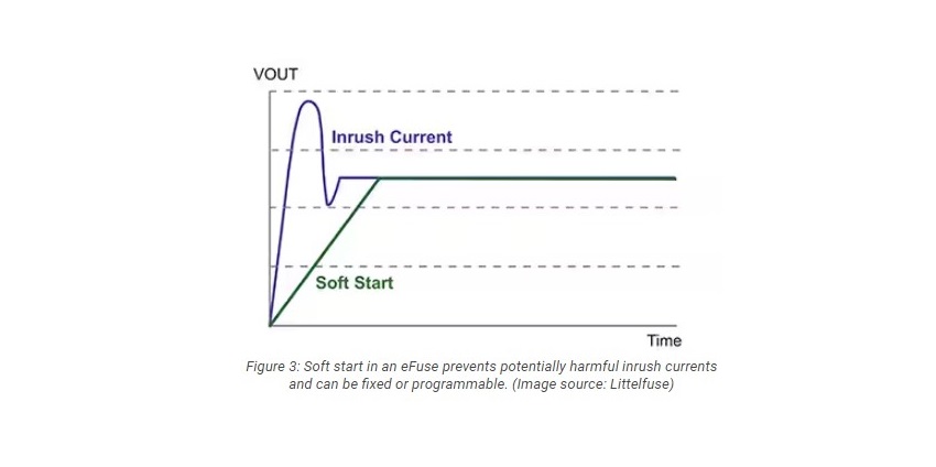
Soft start limits the inrush current flow when a device is turned on. Without a soft start, the only limitations on the current are the relatively low impedance of the printed circuit board (pc board) traces and the components. High inrush currents can damage the power supply circuit or the components.
Soft start slowly turns on the eFuse, providing slew rate control and limiting the inrush current (Figure 3). The soft start rate can be fixed or programmable.
UVLO and OVP
Too much or too little voltage can also result in system malfunctions and possible damage. UVLO in an eFuse prevents the device from operating if the input voltage is lower than a preset threshold.
If the input voltage rises too slowly, the voltage can drop as the load current rises
In addition, if the input voltage rises too slowly, or if the power source has a significant internal resistance (like a battery), the voltage can drop as the load current rises, causing the voltage to repeatedly cross the UVLO threshold. When that happens, the UVLO function can go into oscillation. Using a UVLO circuit with a hysteresis (lag) of about 150 to 300 millivolts (mV) can eliminate oscillations and ensure the smooth operation of the UVLO function.
OVP
OVP protects the device from being stressed or damaged by excessively high voltages. When an overvoltage condition is detected, the eFuse immediately clamps the voltage to protect the system, then turns it off.
It also discharges the output capacitors to the ground through an internal resistor. When the voltage falls to a specified value, the eFuse automatically turns on (Figure 4). The OVP threshold can be fixed or programmable.

Thermal protection
Excessive temperatures can also result in damage or improper functioning, so eFuses include an internal temperature sensor. OTP is typically implemented as a two-stage process.
- First is the thermal regulation temperature, usually around 125°C, at which point the eFuse limits current flow to try and stop the temperature rise.
- If the temperature continues to increase, and the device junction temperature exceeds the thermal shutdown threshold (TSHDN) usually around 140°C, the eFuse turns off. OTP also includes hysteresis, and the eFuse will restart when the internal temperature falls 20°C below the TSHDN (Figure 5).

Compact 5-volt eFuses for battery-powered devices
Designers of Bluetooth headsets, wearables, tablet PCs, and other adapter-powered devices can turn to the 5-volt, 5 A-rated LS0505EVD22 in a DFN2X2_8L package, and the 5-volt, 4 A-rated LS0504EVT233 in a SOT23_3L package for compact solutions that provide OVP, OCP, and soft start (Figure 6).
The 50 milliohms (mΩ) resistance of the internal switch minimizes power dissipation. The OVP reacts immediately in the event of excessive voltage and discharges the output capacitor. The current limit threshold is set with an external resistor, and the OCP operates in hiccup mode for overcurrent or short-circuits conditions. The automatic soft start function provides a smooth voltage ramp-up, limiting the inrush current to a safe level.

18 volt / 5 A eFuses
LS1205E series eFuses are suitable for use in hard disk drives, solid-state disk drives, and adapter-powered devices
The LS1205E series eFuses have an operating voltage range of 2.7 to 18 VDC, a current rating of 5 A, and are suitable for use in hard disk drives, solid-state disk drives, and adapter-powered devices like notebook computers and networking devices.
These eFuses feature a switch with a 25 mΩ on resistance and are in a 10-lead DFN3×3 package. They include programmable soft start time, programmable current limit threshold up to 5 A, short-circuit protection, UVLO, and fold-back OTP. Two models are available:
LS1205EV
The LS1205EV includes three selectable input voltage ranges. The output clamp voltage and UVLO thresholds are based on the selected input voltage range.
The LS1205EF includes an open drain fault indicator function that signals the occurrence of UVLO, OVP, short-circuit, and thermal shutdown faults.
28-volt eFuse with RCB and FRS
Designers of notebooks and tablet computers, docking stations, and network devices that need Thunderbolt or USB Type-C PD functionality with RCB and FRS, can turn to the LS2406ERQ23 28 volt, 6 A eFuse regulator that includes OCP, OVP, short-circuit, soft start and OTP (Figure 7).
LS2406ERQ23 comes in a low-profile, 16-lead QFN 2.5 millimeter (mm) x 3.2 mm package and is UL Recognized
The power switch has a resistance of 24 mΩ to minimize power dissipation during normal operation, the OCP, OVP, and soft start functions are programmable, and the OTP includes automatic recovery when the device cools. This eFuse features an always-on RCB function regardless of the enable signal (EN) logic state. FRS and the integrated input and output discharge functions meet the USB PD specifications. The LS2406ERQ23 comes in a low-profile, 16-lead QFN 2.5 millimeter (mm) x 3.2 mm package and is UL Recognized to UL/CSA 62368-1.

Board layout guidelines
For the LS1205E series, as well as the LS0505EVD22 and LS0504EVT233, here are some general board layout considerations to help ensure a successful implementation:
- A 0.1 microfarad (µF) or larger ceramic decoupling capacitor should be placed between the IN terminal and ground (GND), and between the OUT terminal and GND. When the input power path inductance is negligible, such as in hot-plug applications, this capacitor may not be necessary.
- Decoupling capacitors should be placed as close as possible to the IN, OUT, and GND terminals and the loop area formed by the connections must be minimized.
- High-amperage power traces should be sized to carry at least twice the maximum expected current and should be as short as possible.
- The GND terminal of the eFuse must be connected directly to the pc board ground plane. The ground plane of the pc board should be an island or copper plane.
LS1205E series
For the LS1205E series only: Locate all support components like RILIM, capacitor SS (CSS), and resistors for EN, as close as possible to the corresponding connection pin, and use the shortest possible trace length to connect the other side of the component to GND.
The traces should be placed to prevent coupling to any switching signals on the pc board
The traces should be placed to prevent coupling to any switching signals on the pc board, and the length of the traces for the RILIM and CSS components should be as short as possible to minimize the effect of parasitics on the current limit setting and soft start timing. For the LS2406ERQ23, refer to the datasheet for layout considerations related to USB Type-C cable short-circuit protection and FRS components.
Conclusion
For the protection of both users and devices, and to meet applicable standards, designers can turn to integrated protection eFuse regulators that provide a variety of functions including OVP, OCP, ULVO, OTP, and reverse-current blocking.
With programmable protection thresholds and reset capability, eFuses support design flexibility, while also featuring low “on” resistance switches to maximize efficiency and include a soft start to minimize inrush currents. Some models include certified FRS and RCB for use in USB Type-C AC adapters.


