Over the past decade, Earth-orbit spacecraft have become major industries with mass-market applications. This has resulted in the deployment of large numbers of satellites with a wide variety of missions that are operating in low, medium, and geostationary Earth orbits (LEO, MEO, GEO).
Regardless of their size, source, or mission, all these satellites have one common factor in their bill of materials (BOM): the need for many electrical connectors and cabling for signal and power.
selection and application of interconnects
While these may not have the glamour factor of active onboard electronics or the broader satellite mission, their performance, reliability, and constancy are vital to satellite design, deployment, and target longevity.
As a result, the selection and application of suitable interconnects is an important factor in mission success. They must provide basic functionality while minimizing size and weight, and at the same time, they must meet the unique reliability and ruggedness mandates required for space launch and flight.
requirements of space-qualified connectors
Space-qualified connectors and cabling are standard components available from vendors via distributors
Fortunately, due to the 21st-century need for a relatively high volume of interconnects, space-qualified connectors and cabling are standard components available from vendors via distributors, a major shift from just a decade or two ago when they were specialized, often custom order items.
This article looks at the requirements of space-qualified connectors and cables and their appropriate selection. It then introduces real-world solutions from Harwin that can help ensure mission success.
Cable and connector requirements for space
Once primarily the domain of NASA missions with esoteric spacecraft or communications/navigation satellites, launches of LEO, MEO, and GEO satellites have become almost routine events.
Some of these launches result in the deployment of a dozen or more satellites, including the small, popular CubeSat units developed at universities, some high schools, and even amateur scientific groups.
space as a harsh environment
Potential problems include intermittent connections, sub-specification performance even outright failure
However, space is a harsh environment for electronic components of all types. Potential problem areas include intermittent connections, sub-specification performance, and even outright failure. These problems begin with launch vibration and extend through the cold and vacuum of orbital use and beyond.
These issues place many demands on connector performance as well as constraints on connector design and implementation. They are all united by the broad term of reliability priorities and the impracticality or impossibility of in-flight repair or replacement.
Issues in space applications
Along with size, weight, shock, and vibration, other issues include outgassing, residual magnetism, temperature extremes, thermal cycling, cosmic radiation, flashover, and connector orientation:
- Weight and size (volume): A space vehicle and its satellite are severely constrained in both of these factors for fuel efficiency and the fact that every cubic centimeter of volume is precious in a volume-constrained space design.
- Acceleration, vibration, and shock: The harsh launch phase results in tens of gs across a wide range of frequencies. For this reason, space-rated connectors usually specify jackscrews or latching designs whenever possible to ensure a secure connection.
- Outgassing: The heat and vacuum conditions of space increase the rate of outgassing from connectors. Materials such as elastomers and plastics can slowly release volatile organic compounds (VOCs) which were dissolved, trapped, frozen, or absorbed in the material as a gas or vapor. Even epoxy and other routine adhesives can release these VOCs, mandating special adhesives. VOCs can result in contamination that can seriously affect the performance of mission-critical equipment by interfering with delicate instruments and optical surfaces. For a space-rated connector, VOCs are “driven out” of the material by baking the connectors at an elevated temperature in a vacuum-sealed oven.
- Residual magnetism: This can interfere with the performance of nearby circuits and subsystems, causing misleading readings from precision sensors. Minimizing this may require the use of non-magnetic materials where possible, such as copper alloys.
- Temperature range: The extended range for space-rated connectors is usually -65⁰C to +150⁰C. However, thermal cycling is also a concern: repeated stresses which result from such cycling can induce microcracks and eventually fatigue fractures. Some satellites are designed to rotate to even out their average temperature between sun-facing and sun-shaded sides. This is an inadequate solution for larger satellites as the surface and subsurface can still be subject to significant thermal cycling compared to its deeper insides. In small satellites, such as CubeSats, nearly all components are relatively close to the surface.
- Cosmic radiation: This increases as the operating altitude of the satellite go higher and the Earth’s protective atmosphere thins. The effects of this unavoidable radiation are similar in some ways to the effects of electromagnetic interference (EMI). While the metal enclosure of the spacecraft will provide some level of protection, it may be necessary to include additional shielding on circuit boards or cables that are susceptible to radiation impact.
- Flashover: This is a continuous electric discharge of high current from a conductor to the nearest metal surface. Flashover will occur at different voltage values depending on the density of the air molecules with the vacuum of space as the extreme case, so connectors must have a voltage rating suitable for the altitude.
- Physical considerations: The orientation of the connector and its cable is critical. Satellites are densely packed, and the popular but tiny CubeSats are taking this density to a new level. A single CubeSat unit (U) is standardized at 10 × 10 × 10 centimeters (cm), and a complete CubeSat satellite can be 1U, 2U, 3U, 6U, or 12U in size.
horizontal connectors and mating cable assemblies
If the connector is designed so that cables are oriented vertically at right angles to the circuit board, the boards within the CubeSat cannot be tightly spaced as the connector and cable will interfere.
However, horizontal connectors and mating cable assemblies address this issue by routing the cables from the edge of the pc board sideways around the stack edge, thereby reducing the clearance needed above the circuit board.
One size does not fit all
Instead, there are standards for specific performance attributes such as outgassing
The different voltages, currents, frequencies, and other performance requirements of the various interconnect paths mean that a single connector family would be severely under or over-specified in many situations, and neither of these conditions is acceptable, albeit for different reasons.
Further, there is no single “standard” that defines a space-rated connector. Instead, there are standards for specific performance attributes such as outgassing.
NASA Parts Selection List
The NASA Parts Selection List (NPSL) is used as a guide for the specification of components for space technologies, and components on these qualified parts lists (QPLs) are specific to space applications.
In Europe, space-grade connectors carry the European Space Agency (ESA/ESCC) qualification. A designer selecting connectors must strike a balance between connector ratings and mission criticality.
cost and availability/lead-time issues
It’s important to provide a realistic perspective of project requirements versus connector and cable options
Over specifying connectors can lead to serious cost and availability/lead-time issues. At the same time, it would be unfortunate and frustrating if a CubeSat failed prematurely due to inadequate or poorly understood connector issues.
Therefore, it’s important to provide a realistic perspective of project requirements versus connector and cable options.
Many available choices to match the requirements
To allow designers to optimally tailor their selections versus space-rated mandates, vendors such as Harwin offer multiple connector families. Each family, in turn, has multiple variations in contact type and count, mating arrangement, retention options, and other features. Among the relevant Harwin connector families are:
- The Mix-Tek Datamate range offers a wide range of configurations for signal, power, and coaxial connectors, allowing engineers to select the connector arrangements that are well-matched to their applications. Power contacts are rated up to 20 amperes (A), signal contacts handle 3 A, and coaxial contacts provide 6 gigahertz (GHz) performance with a 50 ohm (Ω) impedance.
The high reliability is due to the use of turned contacts in conjunction with Harwin's four-finger beryllium copper contact clips. Mix-Tek connectors are available in a variety of wire and board-ready configurations with a maximum of 50 low-frequency contacts or 12 special (coaxial and power) contacts. The connectors, with 2 mm pitch, can be mixed and matched with almost any combination of signal, power, and coaxial contacts.
- The Kona 8.5 mm pitch high-reliability connector family provides a high-quality and high-current connection for demanding environments. Individually shrouded contacts achieve 60 A continuous current at 3,000 volts per contact, with a durability rating of 250 mating cycles. The six-finger contact design is beryllium copper and gold plated to maintain electrical continuity under heavy shock and vibration, and is available in a compact single-row package in cable-to-board configurations.
- The M300 power connectors offer a range of high reliability and performance power ratings and achieve a compact power connection with up to 10 A per contact, thus providing a lightweight, robust solution with a proven track record under extreme conditions (Figure 4). The connectors guard against vibration and shock with fitted stainless steel jackscrews.
The proven four-finger contact design maintains electrical continuity despite high vibration and shock environments. These 3 mm pitch pc board connectors, crimp cable connectors, and ready-made cable assemblies are capable of withstanding -65°C to +175°C and are durable for 1,000 mating cycles.
CubeSat drives a special family
Gecko connectors and cable assemblies are designed to match the relatively high volume and less stringent requirements
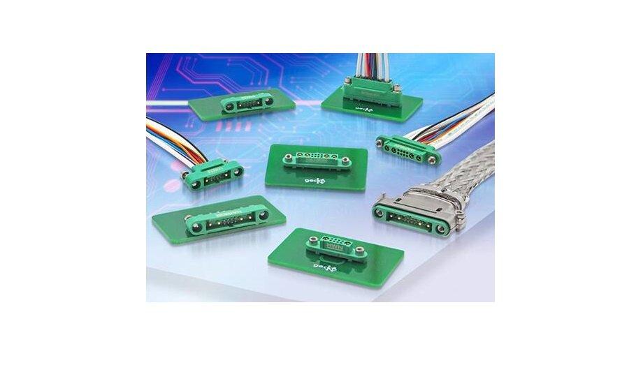
The Gecko family of connectors and cable assemblies are designed to match the relatively high volume and less stringent requirements along some dimensions for CubeSat applications.
These connectors provide a low-profile, cable-to-board, and board-to-board interconnect solution and are especially well-suited for stacking and cable mating in areas where PCB real estate is at a premium.
Gecko connectors
Gecko connectors are 1.25 mm pitch, high-reliability rectangular connectors, and are supplied as connector housings with separately ordered replaceable contacts.
The connectors use cable-barrel crimp contacts, and housings and are available in male and female versions; vertical and horizontal through-hole pc board tail connectors and vertical surface-mount connectors are intended for cable-to-cable, cable-to-board, and board-to-board interconnection.
Gecko variants
The Gecko connectors are up to 45% smaller and up to 75% lighter than existing industry standard equivalents and Micro-D, with a typical weight of about 1 gram (g). They are offered in three variants that are not intermateable:
- Gecko-SL (Screw-Lok) connector series: One connector has floating screws for secure, robust interconnection to its counterpart (Figure 6). Screw-Lock can also have board or panel mount studs for secure circuit board or enclosure retention. Contacts are rated at 2.8 A per contact in isolation and 2.0 A for all contacts simultaneously. These connectors are offered as both horizontal connectors and mating cable assemblies for high-density board stacking.
For example, the G125-3241696M2 is a 16-contact, panel-mount rectangular Gecko-SL connector with a 1.25 mm pitch.
- Gecko-MT (Mixed Technology): These connectors are mixed-layout versions of the Gecko-SL series (Figure 8). By complementing the data contacts with two or four 10 A power contacts in power/data configurations of either 1 + 8 + 1 or 2 + 8 + 2, the Gecko-MT products enable significant space and weight reductions in electronic hardware.
They are available in cable or through-hole configurations, with the same Screw-Lok fixing variations as Gecko-SL connectors, and in a variety of signal (double row) and power (single row) contact configurations. The G125-FV10805F1-1AB1ABP is a 10-position Gecko-MT Receptacle Connector with eight signals plus two power contacts, allowing a single connector to serve both functions.
- Gecko Latch (original design): The male connectors in this family can be equipped with easy-to-release locking latches for secure interconnection to the female mating connector.
The G125-FS12005LOR, a 20-position, surface-mount receptacle connector is an example of the Gecko Latch design. The Gecko-SL and Latch series offer between 6 and 50 contacts in a dual-row configuration. Connector housings are polarized to prevent mismating and have contact number one indicated on the outside of the housings.
additional flexibility
For additional flexibility, the backshells attach to the circuit board rather than the connector
Optional metal backshells that are compatible with both Gecko-SL and Gecko-MT connectors are available to provide mechanical, radio frequency (RF), and EMI protection, such as the G125-9702002 backshell (hood) for 20-position Gecko-SL connectors.
By making the backshells optional, designs that do not require such protection are not burdened with the weight of a connector with a metal enclosure. For additional flexibility, the backshells attach to the circuit board rather than the connector.
Don’t forget the cable and assembly
It’s easy to spend time and energy on connector selection, but that’s only part of the connectivity story, as the cabling associated with a connector is equally important.
Among the interconnect, choices dictated by the signal type and installation are basic wires, twisted pairs, shielded wire, and coaxial cables. Designers have five choices when it comes to obtaining a cable assembly:
- Do-it-yourself (in-house manufacture)
- Use pre-crimped contacts and wires
- Use ready-made cable assemblies
- Specify a complete, made-to-order cable assembly which is a variation of standard products
- Specify a fully customized cable assembly made specifically for the requirements
Due to the wide use of Gecko connectors, many of the needed cable assemblies are available as standard, ready-made items, thus reducing lead time and uncertainty. For example, the G125-FC11205F0-0150F0 is a 12-position cable assembly that is 150 mm long and is designed for rectangular socket-to-socket interconnections.
Conclusion
It is important to look for connectors that are the smallest and lightest possible for the needed performance bracket and not to over-specify where tighter numbers or goals are unneeded. This is especially true in the CubeSat market, as these miniature satellites are designed to be multi-stacked in a rocket where both space and weight are at a high premium.
For these popular, almost “mass market” satellites, Gecko connectors and cable assemblies enable designers to manage the realities of performance and cost as they strive to balance the multiple, sometimes conflicting tradeoffs in component selection.